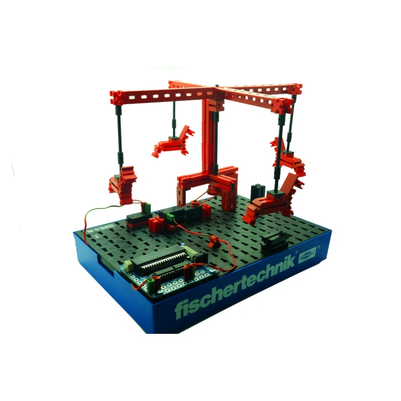
You can find various models of merry-go-rounds at public festivals and amusement parks. The first motordriven merry-go-round was placed in operation on January 1, 1863 in Bolton in England.
Task 1
The merry-go-round is to be started with the push-button switch . It is to rotate for10 seconds and then stop.
Task 2
Just going in one direction is rather boring. Change the program so that it waits asecond after the motor stops and then the merry-go-round turns in the other directionfor 10 seconds.
Seefull online guide withmicro:bit coding samplesfor the Merry-Go-Round model,plus extension activities.
Seemicro:bit coding with input and output guides here.
This is a specially discounted package -delivered in a clear plastic bag.
Each pack comes with thebonus fischertechik storage base (box 250 x 186)
I/O board for micro:bit
micro:bit pins extension board, designed specially to take advantage of fischertechnik’s unique, flexiblered and green round plugcable connections. By design, the I/O board rubber legsslotinto the fischertechnik black base-plate grid securely.
The price below is for 1 model out of the 12 models STEM II pack. If you want to build all 12 models, order the full STEMII packinstead.
The fischertechik advantage
- All model parts can be reused and recycled for other projects and student’s creative pieces. fischertechnik is made in Germany with quality and precision.
- No soldering. Ideal for all ages, promote problem solving, changes on the fly as debugging and adjustment can be done instantly. All works can be done to perfection as even the smallest adjustment can be accommodated, thanks to the complete range of mechanical/structural and electronic blocks offered by fischertechnik.
- One of the 12 models of STEM 2. You can now order it on its own for easy whole class lesson, without needing to pick and sort building blocks every time.
micro:bit code
Part 1 – micro:bit block commands used in the Merry-Go-RoundModel
To achieve fluency and competency in micro:bit coding, you really need to get a thorough understanding of each of the blockcatagories to be used in the Merry-Go-RoundModel (see part 2 below for the full code). Fortunately, all the reference guidesare available on the BBC micro:bit web site for you to get a deeper and more comprehensive understanding and mastery.
Through every fischertechnik STEM II models (12 of them), you can learn, practise, build fluency and confidence in coding.
The Merry-Go-RoundModel used the following micro:bit blocks. You can click to lean more about each of the block catagories. The links bring you directly to the respective part of the BBC micro:bit reference document site, where live codes are included for you to understand, try, and download:
- Basic(basic micro:bit functions and actions): On Start, Show LED, Pause
- Input (events and inputs from sensors): Button is Pressed
- Loops: While Loop(repeat code while aBooleanconditionis true), Repeat
- Logic: If (conditionally run code depending on whether aBooleancondition is true or false)
- Function:Definea function,Callinga function
- Pins(Control currents in Pins for analog/digital signals, servos, i2c,…): Digital Write Pin
Part 2 The “live”Merry-Go-RoundCode – Understand, Edit and Download
The following code has used all the mentioned blocks in Part 1 above.
Comments In English, click the ” ? ” on block to find out the comment (meaning) of the block code.
- If you read this page on a computer with wider screen size, you will be able to see the micro:bit simulator that is fully clickable.
- If you cannot see the code, such as on a mobile phone, please clickthis link instead.
- Click to open the code on the micro:bit website for further editing and modification.
- Click to download this code to your micro:bit for immediate use or to save on your computer.
Online guide
Seefull online guide withmicro:bit coding samplesfor the Merry-Go-Round model,plus extension activities.
Seemicro:bit coding with input and output guides here.
I/O board
| Connector | No. | Description |
| Outputs | 8 |
8 x light/LED 4 x DC motor – 600mA per output |
| Inputs | 6 |
5 x analog/ digital 1 x digital – signal up to 5V |
| I2C | 1 | 1 x connector (SCL, SDA) |
| 5V | 1 |
1 x sensor power supply connection (6-9V power supply) |
| 3.3 V | 1 | 1 x sensor power supply connection |
| Battery | 1 | 1 x battery (6 – 9 V) min 4.5 V |
| Power Supply | 1 | 1 x universal power adaptor ( 6 – 9 V) min 4.5 v |
Reviews
There are no reviews yet.